Description
Exiting new opportunities
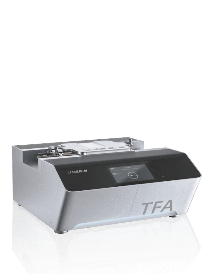
The new Linseis TFA L59 device offers the characterization of physical properties of thin films. It is a highly integrated and easy to use measurement platform.
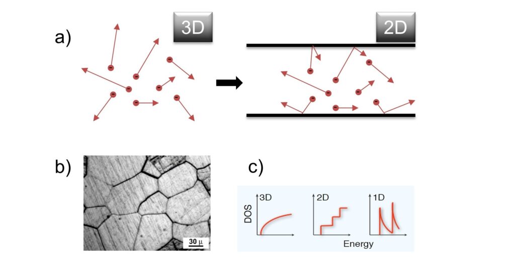
Physical properties of thin films differ from bulk material, as parasitic surface effects are much stronger due to smaller dimensions and high aspect ratios!
- Increasing influence of surface scattering (a)
- Additional boundary scattering (b)
- Quantum confinement for very thin layers (c)
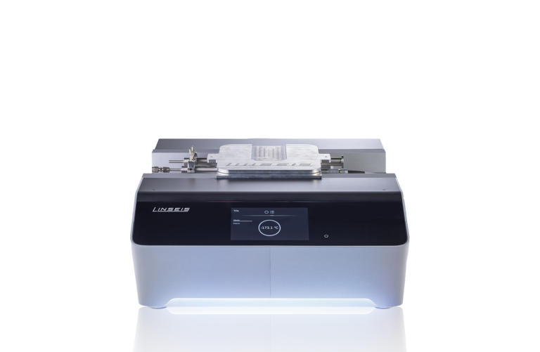
The LINSEIS Thin Film Analyzer is the perfect tool to characterize a broad range of thin film samples in an extremely comfortable and fast way. It is an easy to use, single stand alone system and delivers highest quality results using a patent pending measurement design.
Components of the TFA
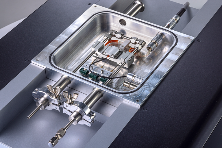
The basic setup consists of a measurement chip on which the sample can be easily deposited, and the measurement chamber to provide the required environmental conditions. Depending on the application, the setup can be utilized with a Lock-In amplifier and / or a strong electric magnet. The measurements are usually taken under UHV and the samples temperature can be controlled between -160°C and 280°C during the measurement using LN2 and powerful heaters.
Pre structured measuring chips
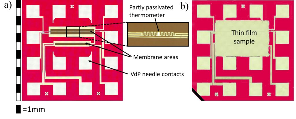
The chip is combining the 3 Omega measurement technique for the thermal conductivity measurement with a 4-point Van-der-Pauw setup for the determination of the electrical transport properties.
The Seebeck coefficient can be measured using additional resistance thermometers located near the Van-der-Pauw electrodes. For an easy sample preparation either a strip off foil mask or a metal shadow mask can be used.
This configuration allows for a nearly simultaneous characterization of a sample which has been prepared by either PVD (e.g. thermal evaporation, sputtering, MBE), CVD (e.g. ALD), spin coating, drop casting or ink-jet printing in one step.
The big advantage of this system is the simultaneous determination of a broad range of physical properties within one measurement run. All measurements are take in the same (in-plane) direction and are very comparable.
1. Van-der-Pauw measurement
To determine the electrical conductivity (σ) and Hall coefficient (AH) of the sample, the Van-der-Pauw method is used. After depositing the sample on the chip, it is already connected to four electrodes A, B, C & D at their edge.
For the measurement, a current is applied between two of the contacts and the corresponding voltage between the remaining two is measured. By clockwise changing of the contacts and repeating of the procedure, the resistivity of the sample can be calculated using the Van-der-Pauw equation. By applying a magnetic field and measuring the corresponding change of the diagonal Van-der-Pauw resistance, the Hall coefficient of the sample can be calculated.
2. Seebeck-Coefficient measurement
For the determination of the Seebeck Coefficient, an additional thermometer and heater is placed on the chip near the sample. This configuration allows for the measurement of the thermovoltage at different temperature gradients which can be used in order to calculate the Seebeck Coefficient S=-Vth/∆T.
3. Thin film thermal conductivity measurement
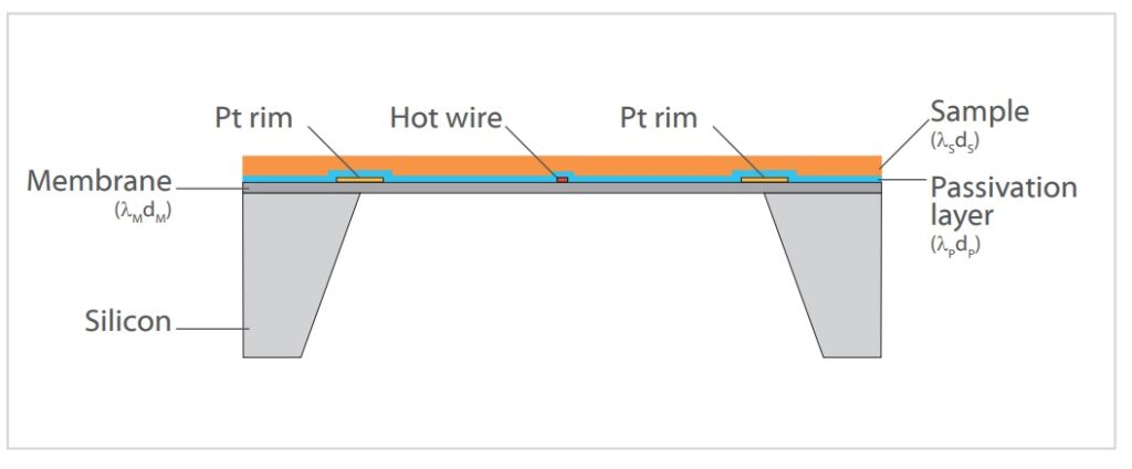
For the determination of the in-plane thermal conductivity, a patent pending hot-stripe suspended membrane setup is used. In this setup, a very small wire is used as heater and temperature sensor in one. The sample of interest will be deposited directly on this membrane. For the measurement in consequence, a current is applied to the hot-wire which is heated up due to Joule heating. Because of the temperature rise, the resistivity of the wire is changing and can be measured easily.
From this resistivity change and the knowledge of the exact geometry of the setup, it is possible to calculate back to the thermal conductivity of the sample. Depending on the sample, it is also possible to measure the specific heat. In order to get high quality results, the sample thickness times sample thermal conductivity should be equal or bigger than 2 x 10⁻⁷ W/m*K.
Modular design
Starting with a basic setup to measure the thermal conductivity, the system can easily be upgraded with either the thermoelectric kit to measure the electrical conductivity and Seebeck coefficient or with the magnetic upgrade kit to take Hall constant, mobility and charge carrier concentration measurements.
System configurations
Basic system / Thermoelectric kit / Magnetic kit / Cooling option
Following packaging options are available for the LINSEIS Thin Film Analyzer (TFA L59):
Basic device (incl. transient package)
Consists of measurement chamber, vacuum pump, basic sample holder with included heater, system integrated lock-in amplifier for the 3ω-method, PC and LINSEIS Software package including measurement and evaluation software. The design is optimized to measure following physical properties:
- λ – Thermal Conductivity
- cp – Specific Heat
Thermoelectric package
Consisting of extended measurment electronics (DC) and evaluation software for thermoelectric experiments. The design is optimized for measuring the following parameters:
- ρ – Electrical Resistivity / σ – Electrical Conductivity
- S – Seebeck Coefficient
Magnetic package
Two different configurations for the magnetic package are available. Either a movable electromagnet (EM) with power supply, field switch, safety circuit and water cooling or a movable configuration with two permanent magnets (PM). The electromagnet allows the user to apply a variable field strength between +/- 1 Tesla perpendicular to the sample. The permanent magnet setup can only be used to apply three defined field points (+0.5 T, 0T and -0.5T) to the sample. Both design are optimized for measuring the following parameters:
- AH – Hall Constant
- μ – Mobility (calculation depending on model)
- n – Charge carrier concentration (calculation depending on model)
Low temperature option for controlled cooling
- LN2 cooling down to -160°C
- TFA/KREG controlled cooling unit
- TFA/KRYO Dewar 25l
Unique Features
Temperature dependent measurements (-160°C up to +280°C)High flexibility for different materials, thicknesses, resistances and deposition methodsHigh quality, easy to use characterization system for thin films (nm to µm range)All measurements in a single measurement run on the same sample and direction for semiconductors, metals, ceramics and organic materialsSpecifications
Special features
- High-quality and user-friendly measuring system for thin layers (in the nm to µm range).
- Enables temperature-dependent measurements from -160°C to +280°C.
- Easy sample preparation and handling.
- Chip-based measuring device with fully integrated, pre-structured chips as consumables.
- Designed for maximum flexibility (material, thickness, resistance, deposition methods).
- All measurements are performed in a single measurement run on the same sample and in the same direction.
- Semiconductor samples as well as metals, ceramics or organic materials can be measured.
| MODEL | TFA L59 – THIN FILM ANALYZER |
|---|---|
| Temperature range: | RT to 280°C -160°C to 280°C |
| Sample thickness: | From 5 nm to 25 µm (depending on sample) |
| Measuring principle: | Chip-based (pre-structured measuring chips, 24 pieces per box) |
| Separation techniques: | Among others: PVD (sputtering, vaporisation), ALD, spin coating, ink-jet printing and many more |
| Measured parameters: | Thermal conductivity (3 Omega) |
| Heat capacity | |
| Optional: | Electrical conductivity / specific resistance Hall constant / mobility / charge carrier density (electromagnet up to 1 T or permanent magnet with 0.5 T) |
| Vacuum: | ~10E-4mbar |
| Electronics: | Integrated |
| Interface: | USB |
| Measuring range | |
| Thermal conductivity: | 0.05 to 200 W/m∙K 3 Omega method, hot-strip method (in-plane measurement) |
| Electrical conductivity: | 0.05 to 1 ∙ 106 S/cm Van der Pauw four-probe measurement |
| Seebeck coefficient: | 5 to 2500 μV/K |
| Repeatability & Accuracy | |
| Thermal conductivity: | ± 3% (for most materials) ± 10% (for most materials) |
| Resistivity: | ± 3% (for most materials) ± 6% (for most materials) |
| Seebeck coefficient: | ± 5% (for most materials) ± 7% (for most materials) |
Software
In addition to the utilized hardware, the powerful Microsoft® Windows® based LINSEIS thermal analysis software performs the most important function in the preparation, execution and evaluation of thermoanalytical experiments. With this software package, Linseis offers a comprehensive solution for programming all device-specific settings and control functions, as well as for data storage and evaluation. The package was developed by our in-house software specialists and application experts and has been tested and improved for years.
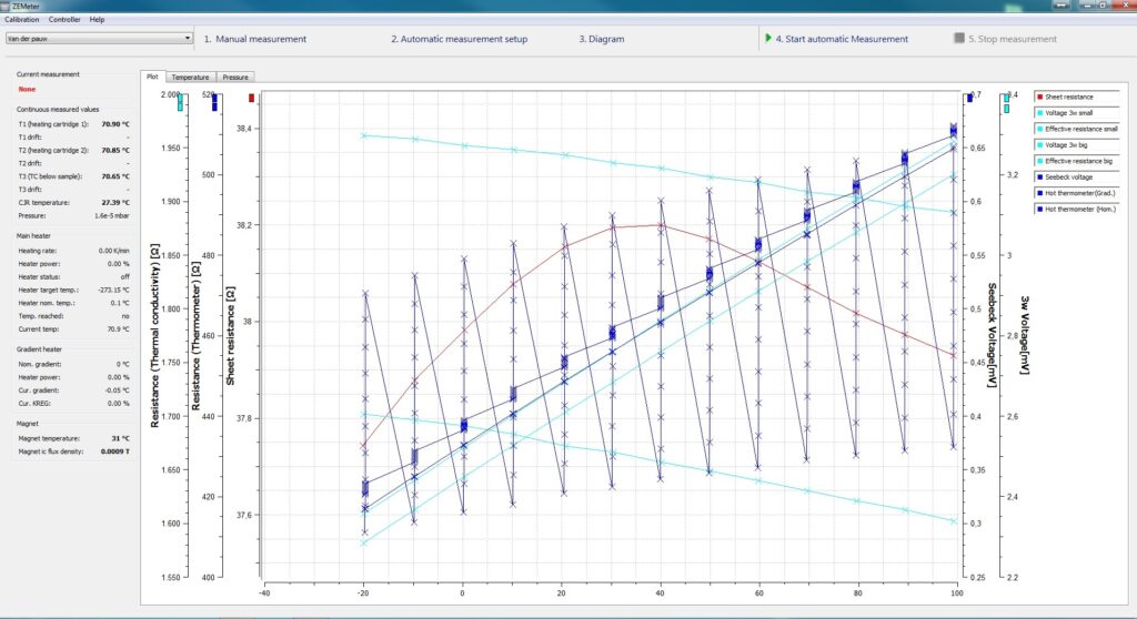
The TFA software package consists of 2 modules: The measurement program for the data acquisition and an evaluation software with pre-defined plugins for the data evaluation. The Linseis software encounters all essential features for measurement preparation, execution and evaluation.
General Features
- Fully compatible MS® Windows™ software
- Data security in case of power failure
- Automatic control of sample contacts
- Thermocouple break protection
- Evaluation of current measurement
- Curve comparison
- Storage and export of evaluations
- Export and import of data ASCII
- Data export to MS Excel
- Easy export
- Database for archiving all measurements and evaluations
- Online Help Menu
- Statistical curve evaluation
- Zoom option for curve analysis
- Integrated evaluation plugins
- Any number of curves can be loaded for comparison
Measurement Software
- Easy and user-friendly data input for temperature segments and measurement tasks.
- Software automatically displays actual measured raw data
- Fully automated measurement
Evaluation Software
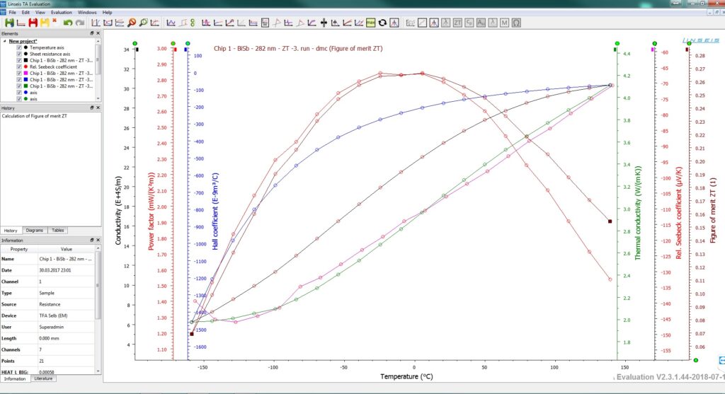
- Pre-defined evaluation plugins (according to published models)
- Alternatively: Direct access to the raw data
- Direct evaluation of the measured data for the calculation of
- Thermal conductivity
- Specific heat
- Resisitivty / Conductivity
- Seebeck Coefficient
- Easy data plotting and data export
Applications
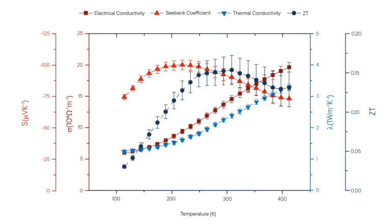
Application example: Bismuth-antimony thin film
Measurements of a 142 nm thick bismuth-antimony film produced by thermal evaporation under vacuum conditions in the temperature range from -160°C to + 140°C .
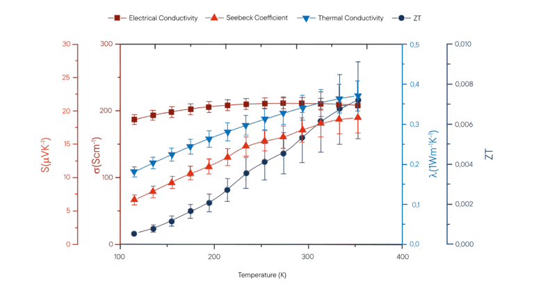
Application example: PEDOT:PSS thin film
Measurements of a 15 µm thick PEDOT:PSS film (High Conductive Grade), which was produced by drop coating, in the temperature range from -150°C to +100°C.
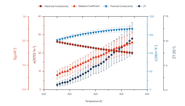
Application example: Gold nanofilm
Measurements of a 100 nm thick Au film produced by DC magnetron sputtering under vacuum conditions in the temperature range from -50°C to +100°C.